Structure and Use of Mechanical Cardshaft Single Plate Rotary Cutting Machine
The mechanical card axis veneer rotary cutting machine is the core equipment for plywood production. It clamps the wood segment with a card axis and drives it to rotate, and completes veneer processing with a rotary knife. It has a compact structure and flexible operation, but the degree of automation is relatively low, making it suitable for application in small and medium-sized enterprises.
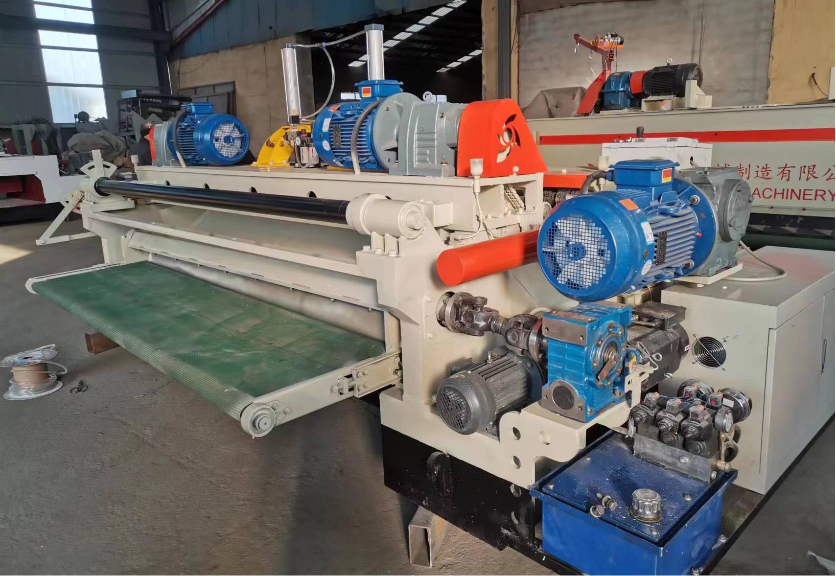
Core structure analysis
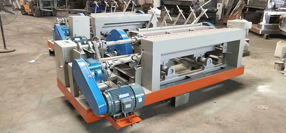
dynamical system
Mainly using AC electromagnetic speed regulating motors, power is transmitted to the card shaft through belts or couplings, with a speed range of 125-1250r/min, supporting stepless speed regulation. Some models use DC motors to enhance overload capacity, but the cost is relatively high.
Cardshaft transmission mechanism
Adopting a single card axis design, axial feed is achieved through screw drive. The front end of the card shaft is equipped with a replaceable chuck, and the large-diameter wooden section needs to be cut in two rounds, while the small-diameter wooden section can be completed in one round. The braking device achieves rapid braking through the linkage between the car brake band and the spring.
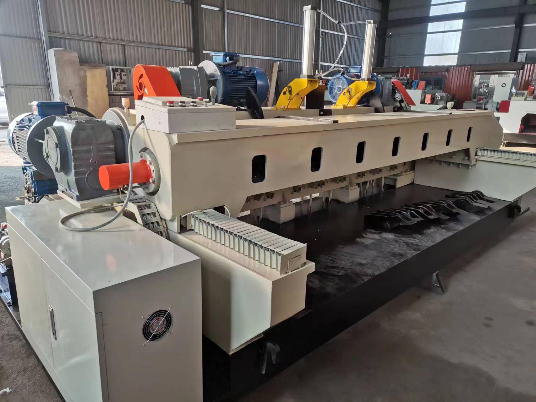
Knife holder and pressure gauge system
The tool holder is driven by gear transmission for feed, and the rotary blade works in conjunction with the pressure gauge holder. The pressure gauge holder adjusts the gap between the blade and door through an eccentric sleeve or slider to meet the requirements of different thicknesses of single boards. The rapid advance and retreat mechanism is driven by an independent motor to shorten the auxiliary time.
Machine base and protective system
The overall structure adopts a cast iron base and is equipped with a protective cover to isolate dust. The head box and tail box are integrated with components such as bearings and copper sleeves to ensure the accuracy of the shaft rotation.
Operation process and precautions
Clamping and debugging
Insert the two ends of the wooden section into the card shaft, adjust the initial position of the pressure gauge, and set the thickness of the veneer by changing the gears through the feed box. Before starting the main motor, check the tension of the brake band.
Rotary cutting control
The main motor drives the card shaft to rotate, and the feed system advances the tool holder according to the preset thickness. During the rotary cutting process, it is necessary to monitor the changes in the diameter of the wood segment and adjust the feed rate in a timely manner to maintain a constant cutting speed.
Maintenance points
Regularly replace worn brake belts and V-belts, and check the lubrication status of the lead screw. Clean and lubricate the transmission gears monthly, and check the coaxiality deviation of the shaft every quarter.
The mechanical card shaft rotary cutting machine balances cost and efficiency through modular design, but due to limitations in mechanical transmission accuracy, its single board thickness stability is slightly inferior to hydraulic models. Operators must strictly follow the process parameters to avoid cracks or thickness deviations on the back of the veneer caused by fluctuations in feed rate.